Tutorial 24: Advanced Connect Shape Workflow with Data Points in Cavalry
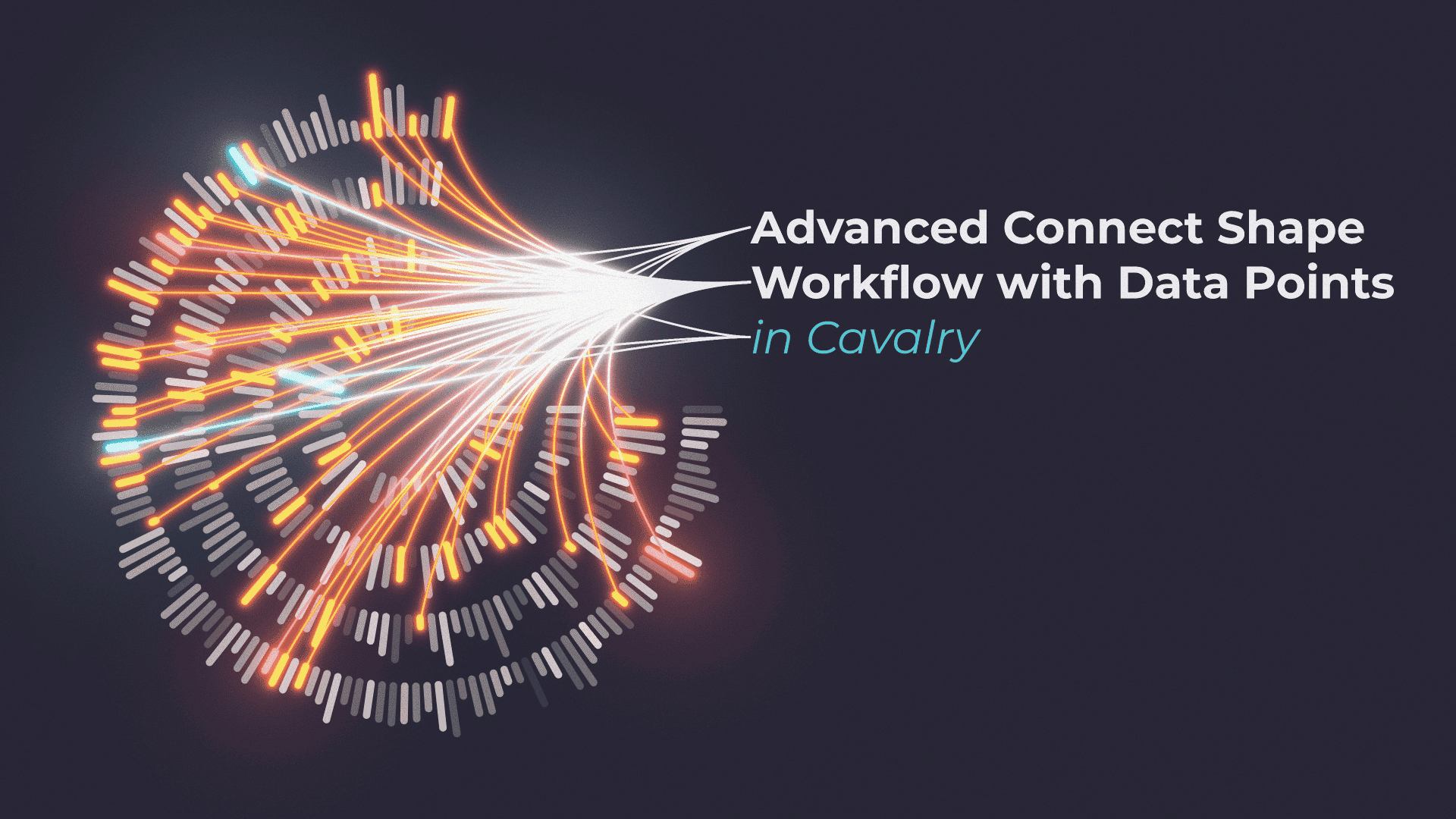
In this tutorial, I will show you how to set up FUI type of graphics, that is animated with 1x Noise layer. This tutorial is a bit longer and more complex, than a simple technique or a workflow. I’m using quite a few nodes in the whole set up, using different types of nodes and “feeding” the data from one node to another to achieve final design.
I’m calling it FUI type of graphics, as at one point in the workflow, I can’t get the Connect Shape layer to correctly connect to specific “data beans” / data points. I suspect that this is due to the fact, that I’m offsetting Context Index for base Duplicator and Connect Shape node is connecting to wrong nodes further up the chain.
I can’t seem to be able to fix it, but I was able to find a “happy medium” solution in the end.
Index Context, all about Index Context
I would recommend reading Context page on Cavalry Docs. In this tutorial, I have used it to increase the size of each “Data Ring” as it gets Duplicated. Putting Duplicator (A) into Duplicator (B). Then sending Duplicator (B) Context Data, to Duplicator (A), to get bigger and bigger data rings with each copy.
This results in each ring increasing the size with Index Context from Duplicator (B). And I used the same technique, to increase the number of copies of “data points” on each ring, with each copy.
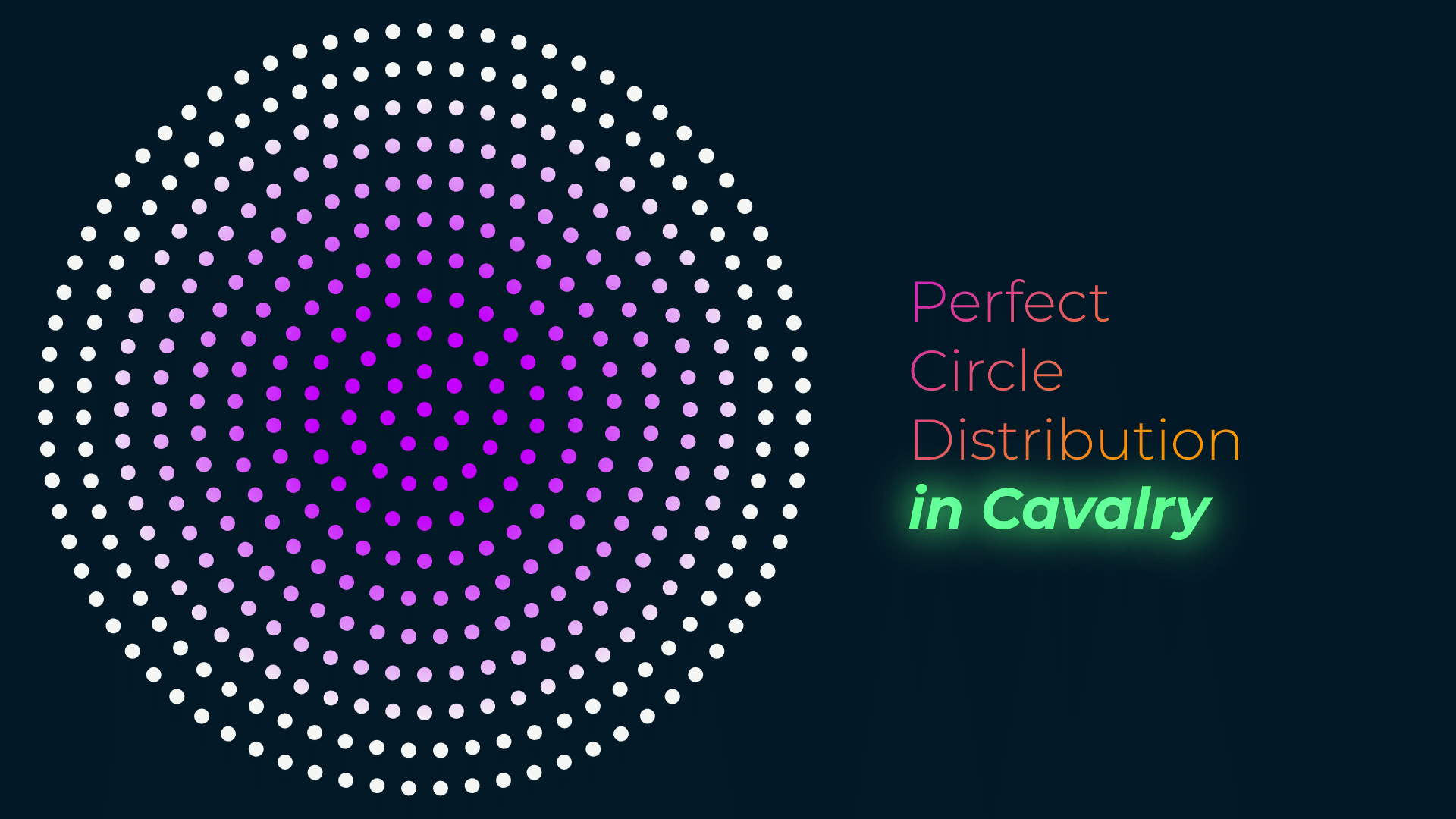
You can see this clearer in the attached simple example, without any animation and size variation. This makes the design more balanced, more precise and more FUI-y 🙂

Logic Gates
Second most important tool that I used in this tutorial was use of Logic Gates:
These tools allow us to set up logical operations very easily – if A is bigger than B, show A. Otherwise show B. By combining them with each other, I can easily set up a Boolean Range of sorts. In the tutorial, this happens, when I am setting up 2nd Connect Shapes rig.
This is a great way of selecting data precisely and getting Boolean output – True or False. In initial test, I was using JSMath node, but I realised that I can simply use Comparison and Logic tools, that are built in right inside the Cavalry.
Anchor Point – Center
This code pushes Anchor Point of any layer, to dead center of the layer it is applied to. By defining different sides, like left and top as variable, we can use it in final array calculation. Simple math helps push and offset Anchor Point to the place we need.
Position – In the Middle of Composition
This simple expression puts position of the layer in the middle of composition. Simple to use and very effective – it is dynamic and adjusts itself to any composition size.
This project file contains all the assets necessary to make animation in the tutorial in final form. Everything is labeled, linked, with expressions and ready to use, if you wish to make your own version or just play around with it.
If you have any suggestions for tutorials or how I can improve, please do get in touch. I would love to hear from you.


